History

Figure 1. Miniature Phalaenopsis orchid
I know that this does not look like an electronic project but it does represent the reason I became interested in electronic devices and circuits.
Some time ago, I installed a small greenhouse for my collection of tropical plants. The next day, the temperature in the greenhouse was 105° F. Since cooking is not one of my hobbies, I needed to lower the temperature. There was a 12 volt ac (alternating current) line intended for low voltage outdoor lighting near the greenhouse so I looked for a 12 volt ac fan. There was none available but there were large numbers of 12 volt dc(direct current) fans intended to be used in an automobile and powered by the auto 12 volt battery via the cigarette lighter socket.
All I had to do was convert 12 volts ac to 12 volts dc and I could cool the green house with a fan.
What I learned was that ac to dc conversion was a simple electronic task accomplished with a module called a rectifier made up of one or more diodes. So I built a rectifier and powered a fan and cooled the greenhouse. In the process, I found electronics and electronic device construction fascinating and a new hobby was born.
I went on to install a thermostat in the green house to turn the fan on and off at set temperatures and then plumbed the green house and set up a sprinkler with a solenoid valve activated with a hygrometer(humidity sensor) that would mist the plants if the air got too dry. By then, I was firmly hooked on electronics.
I set out to acquire surplus electronic parts and circuits, draw a schematic of the components and figure out how the gizmo worked. I decided to learn vacuum tube circuits then transistor circuits and last, integrated circuits to follow the historical progress of electronics.Since music and guitar playing are among my hobbies I found that circuits that can (or can be made to) make noise or music were of special interest.
Ultimately, I designed and built an electronic organ that incorporated a wide range of components and circuits and combined my interest in carpentry and furniture making with electronics and music.

Figure 2. Electronic Organ
The basic schematic for the musical components of the organ are:

Figure 3. Electronic Organ Musical Component Schematic.
On top of the organ is a sound effects generator that was my next project. It is built around an integrated circuit that is capable of generating a wide range of sound effects including explosions. I used it to add cannon blasts when playing the 1812 Overture on the organ.
The sound effects generator panel looks like this:
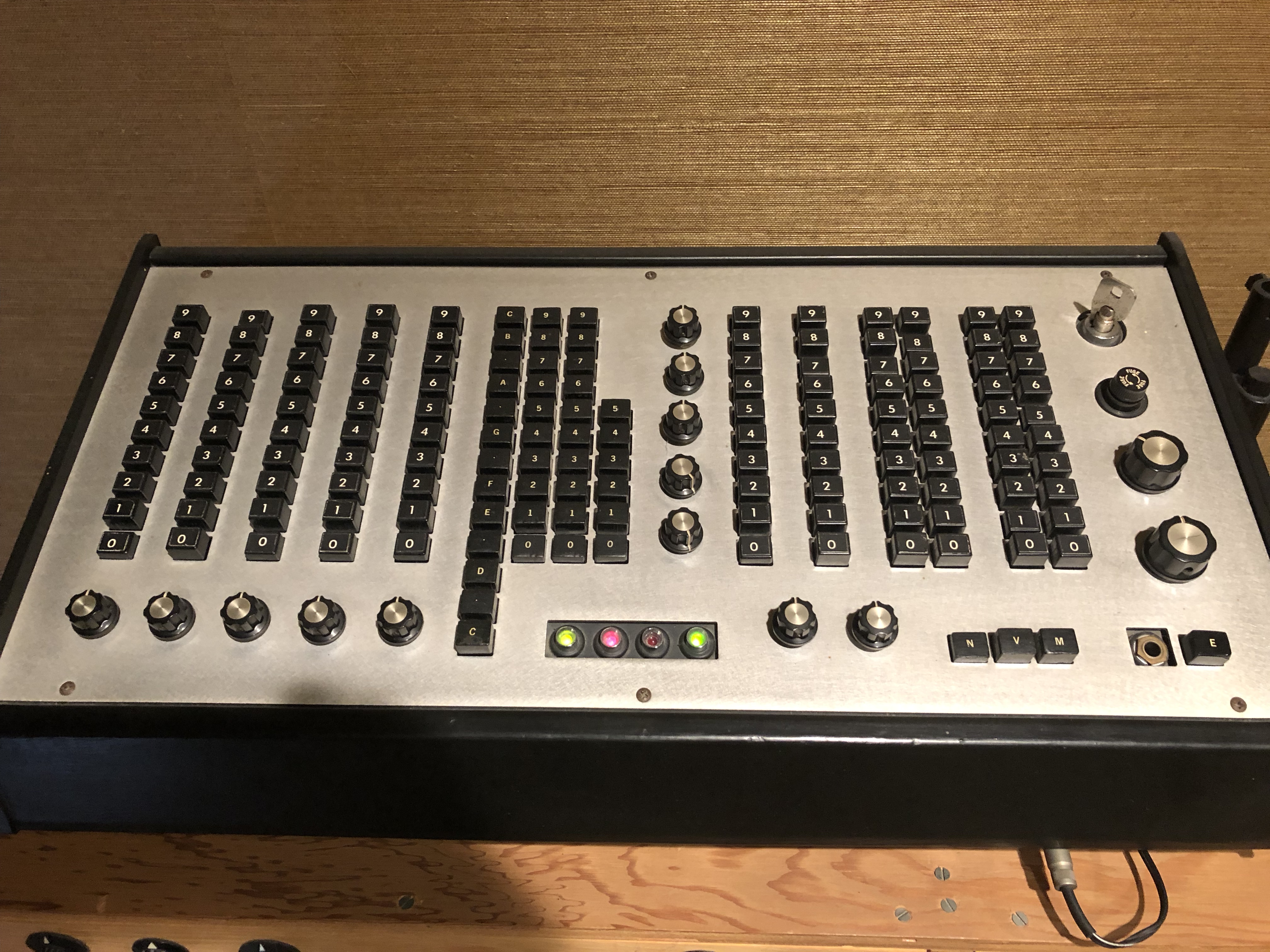
Figure 4. Sound Effects Generator
And the knob and button functions are noted here:

Figure 5. Sound Effects Generator Front Panel Functions
In Figure 3, at the bottom of the sound effects generator panel you can see four light emitting diodes (LEDs). From right to left, they are green, off, red and green. The green light on the right indicated that the unit is powered on. The next light, off in the photo, lights red when a button in the right lower corner of the unit is pressed to initiate a sound manually.The red and left-most green LEDs indicate the state of two control circuits of the sound effects generator that trigger parts of a single sound or cause alternating sounds to be produced. Each LED is red if its control signal is positive and green if its control signal is negative. These LEDs are called Bi-color LEDs since the red and green LEDs are in a single clear plastic unit.
The circuit that senses the state of the control circuit and lights a Bi-color LED red or green is the one circuit in all of my electronic construction that I designed completely from scratch and it is the subject of its own section called “Bi-Color LED Driver”.

You must be logged in to post a comment.